
The Decision To Install Lithium
In 2015 we found ourselves in San Diego replacing our main engine. I’ll describe that in a future post. Months later we made the decision to replace the batteries. We’d seen enough battery horror stories among the cruising community in Mexico to know we wanted batteries that were safe, reliable and long lived. We chose lithium batteries. You can read about how we decided lithium batteries were the best option in the post, The Lithium Question.
If your first reaction is, Lithium batteries on a boat? You’re Crazy! Go read that post, comment on it if you think I’m wrong, and then come back.
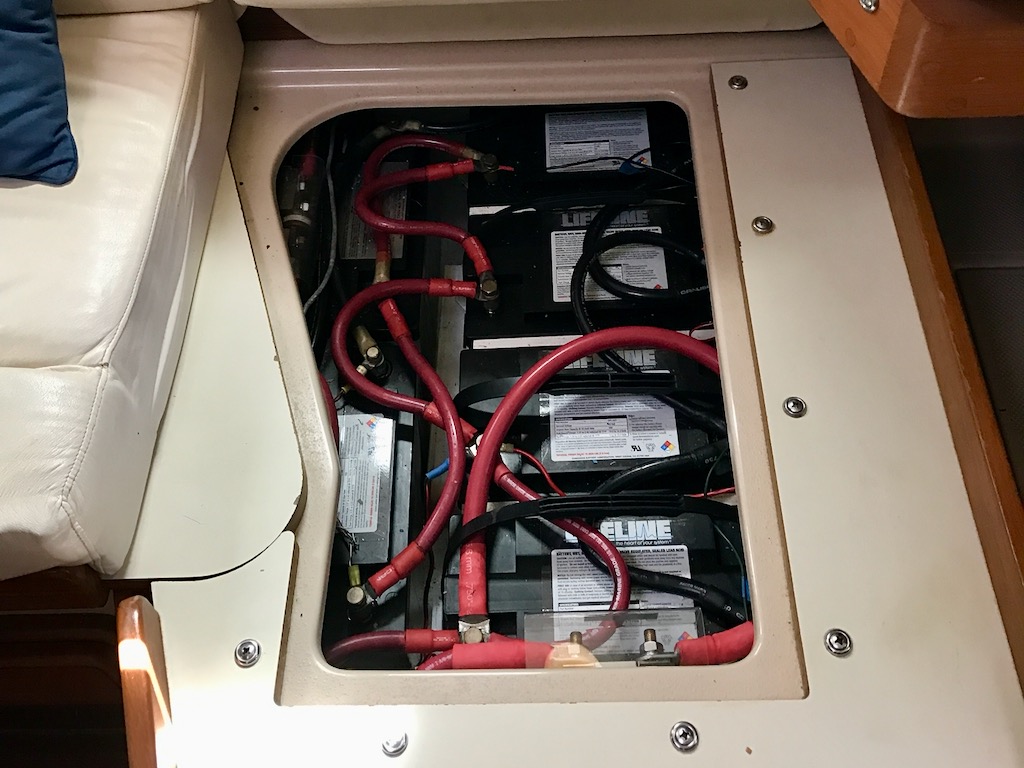
Karvi came to us equipped with six Group 27 Lifeline AGM batteries that were rated at 100 amp hours each. 600 amp hours of AGM batteries gave us 300 usable amp hours due to the 50% rule imposed by lead acid technology. 300Ah worked okay, but we wanted to add some new creature comfoerts like a high capacity water maker, a TV, Air Conditioning, and things that needs to be recharged like drones, computers, smart phones, etc. More energy was needed. The problem with adding more amp hours to a boat is where to put it? I’ve seen cruisers put extra batteries in all kinds of places, including the bilge. Not a good idea. So I started looking at lithium.
My good friend Rob on SV Dolphin who was working as a Jaguar/Land Rover engineer. He and I had been talking about lithium batteries for a long time. We both had a good sense lithium was the way to go, but where to start? Then I ran into Mark on SV Jolly Dogs. Mark is a retired Boeing engineer. Jolly Dogs is a Seawind 1160 Catamaran. Mark didn’t want to weigh Jolly Dogs down with heavy cruising gear so had already installed lithium batteries. After a lot of discussion, more study and a search for suppliers, we decided lithium it was. Not only did we go for lithium, but 4 other boats who were in San Diego at the time (SV Dolphin, SV Silver Sea, SV Jhana, and SV Dazzler) threw their lot in with us. By joining together we were able to get a volume discount.
The Planning
The first question was, how many batteries and how will they fit? I used a 3D CAD program called SketchUp to lay out the batteries in the compartment. I’m not a 3D CAD expert, so it took some learning curve before I could get the hang of it. But once I got going, it was fairly straight forward. In my working career we used to say, “No good deed goes unpunished”. Since I produced a CAD design for Karvi, I ended up producing a CAD designs for the other 4 boats as well. Cruisers helping cruisers.
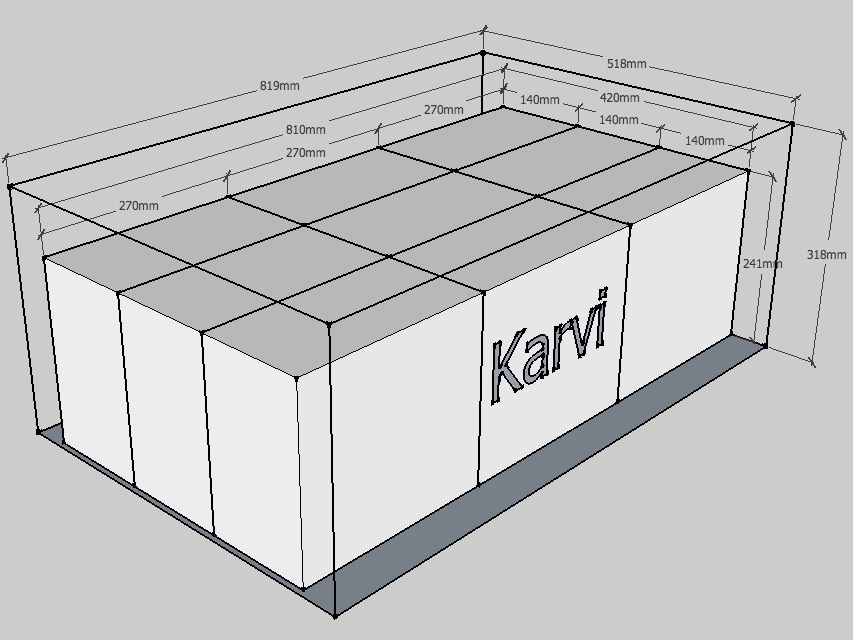
From the CAD exercise, I found Karvi’s battery compartment could hold nine 100 amp hour lithium battery packs. Not only was I able to increase the number of stated amp hours by 50%, I was able to massively increase the number of usable amp hours. Lithiums can use 80% of their capacity while lead acid can use only 50%. Our usable battery capacity increased from 300 amp hours to 720 amp hours and we saved weight to boot. Nine lithiums weigh 252 pounds versus 383 pounds for six AGM batteries.
Our usable capacity increased by an amazing 140% from 300 to 720 amp hours.
Getting Started
The first thing I needed to do was work out the distribution system and and the wiring for the BMS. My plan was to put everything into the battery compartment along side the batteries. In my CAD modeling I had a small amount of space along the side of the battery bank where everything would fit in. But there was a problem:
We needed a “Keep Alive Battery”.
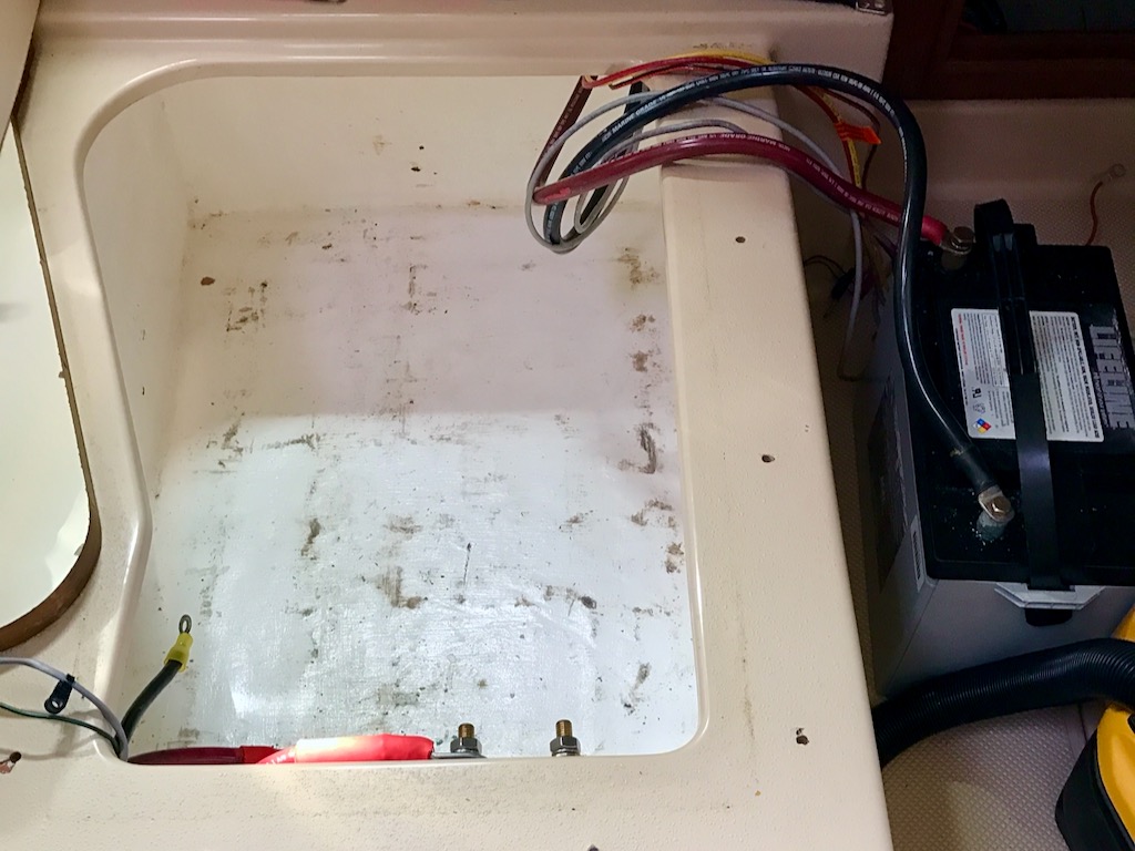
At the time, we were in a marina on shore power but all the lighting, water pumps, toilets, refrigerator, etc. are 12 volt DC. The project was going to take 2 to 3 days. We needed 12 volt power while the project was going on – we needed a “Keep Alive Battery”. The problem was solved by putting one of the AGM batteries outside the battery compartment connected with long cables. The shore power and our inverter/charger kept it topped off while the lithium installation proceeded.
DC distribution means separating the chargers from the loads. This is necessary for the Battery Management System (BMS) to work properly. Sorting out the DC distribution isn’t as bad as it sounds, it’s just a tedious. Normall, a main cable connects from the positive side of the battery bank to a main cutoff switch. From there cables branch out to the various chargers and loads. I just had to follow the cables and sort them out. On Karvi’s load side, there is a DC circuit breaker panel, so one branch goes to the panel. There are two other branches to the electric anchor windlass and the bow thruster.
Topé! Topé! Topé!
Topé is Spanish for speed bump. In Mexico they put topés in places you least suspect them like in the middle of a stretch of highway. We ran into a topé.
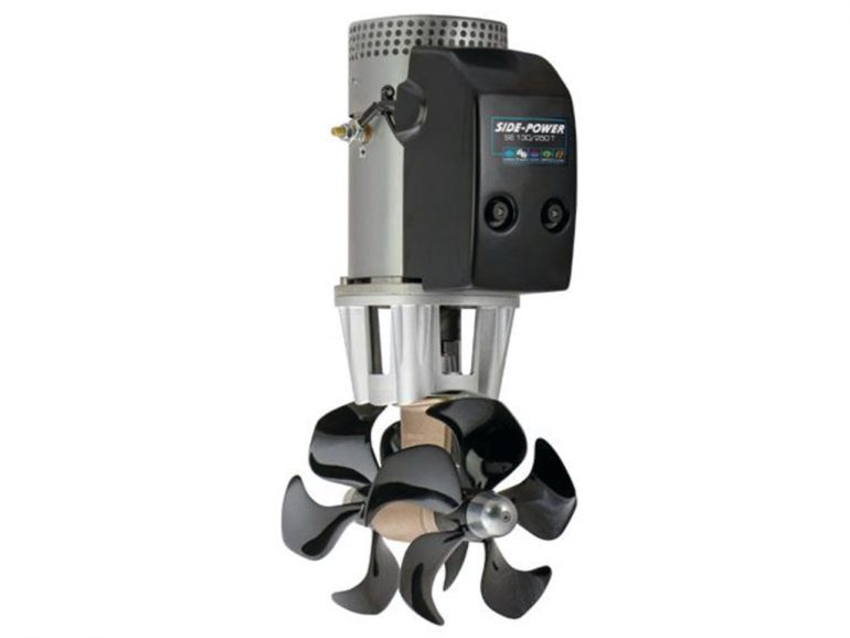
The bow thruster on Karvi is electric and it’s 6.5hp. The specs say it draws 325amps. That’s a whole lot of amps. It’s also a good 25 feet from the battery bank. If you know about current flow and voltage drop, you know that delivering 325amps for a 50ft round trip requires a BIG cable. The installed cable was 4/0 (pronounced four ought). That’s about the biggest cable you’ll find on a boat. As we traced that 4/0 cable from the main cutoff switch, we found burned insulation and about 10 inches of the copper had welded itself into a solid rod. Yikes!
10 inches of the copper had welded itself into a solid rod
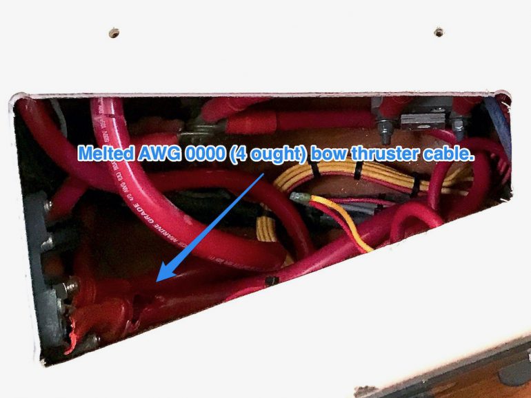
Bow thrusters are meant to be used intermittently and for short bursts only precisely because of the amount of power they draw. Clearly someone in the past had leaned on the bow thruster for a very long time. Perhaps they were auditioning for the boat circus and wanted to impress the judges with a bow thruster triple axle. Whatever the reason, whoever did it is lucky the boat didn’t turn into a carbon slick.
We had to replace the bow thruster cables. Marine cable isn’t cheap and running 50ft of heavy cable through the boat involves a significant amount of boat yoga. Voltage drop/current calculations revealed 4/0 cable isn’t big enough to handle the 50ft round trip. So we replaced the 4/0 with double 2/0 cables. The double 2/0 cables can handle more amperage than one 4/0 cable. It’s not ideal, but it solves the safety risk until an additional battery pack is installed at the bow thruster as a booster.
Charge and Discharge Distribution Buses
We lost a couple of days to the bow thruster cables. That’s life. It was time for the distribution buses. A bus is simply the road system of cables and wires. Along the Charge Bus the power flows toward the batteries to charge them. Along the Discharge Bus power flows away from the batteries to power components on the boat. For most boats the charging and discharging are comingled on the same bus. There’s normally a switch to disconnect the batteries from the bus altogether, but there’s only one bus and everything branches from that bus. If you read about the Battery Management System (BMS) in the companion post The Lithium Question, then you already know the BMS has the capability to disconnect each bus individually according to the battery state. For the BMS to work, the charging sources must have their own bus separate from the discharge bus. As I mentioned above, it’s more tedious than hard but there are a couple of tricky parts.
The Charge Bus
On Karvi we have five ways to charge the batteries:
1. Shore Power
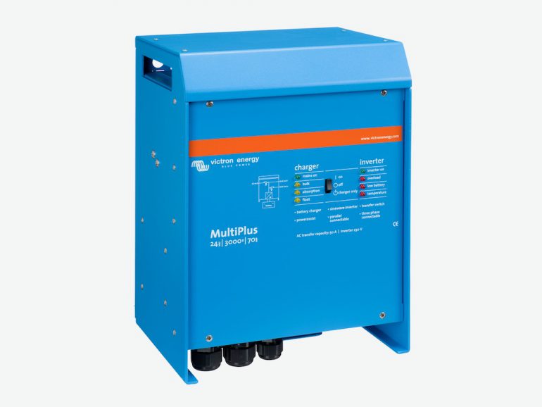
Victron Inverter/Charger
120 amps
A charger charges the batteries. An inverter converts 12 volts into 120 volts. Some boats have separate units to handle those two functions, Karvi doesn’t. Karvi has a Victron MultiPlus 3000, a combination unit that does both. Going with a combo unit saves space on the boat. The downside is that there is only one set of 12 volt cables running to the unit for both charging the batteries and providing the 12 volts to be converted into 120 volts, a discharge function. Fortunately Victron thought ahead. The Multiplus 3000 is programmable so the BMS has a way to tell it to stop charging or stop inverting.
2. Diesel DC Generator
Kubota Diesel with an Alternator
150 amps
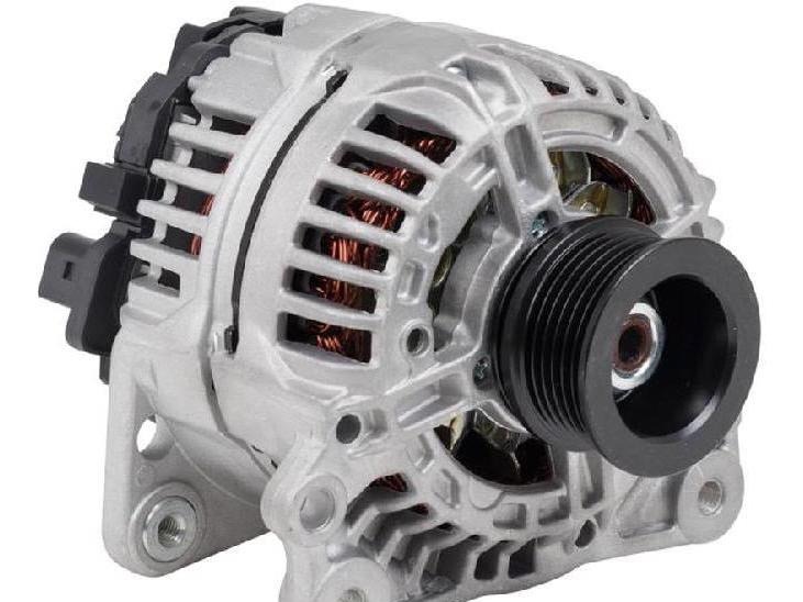
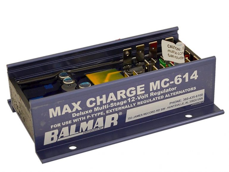
The problem with today’s chargers is that most are MPPT (Maximum Power Point Tracking). MPPT is way to charge lead acid batteries in 3 phases. Lithiums batteries don’t need 3 phases, they only need 1. Most alternators are manufactured with internal regulators. To work with lithium batteries they must be modified to use an external programmable regulator. Karvi has two alternators, engine and generator. We had the alternators modified at a local auto electric shop and purchased a couple of Balmar external programmable regulators.
3. Main Engine
Yanmar Diesel with Alternator
100 amps
Same configuration as the DC Generator above.
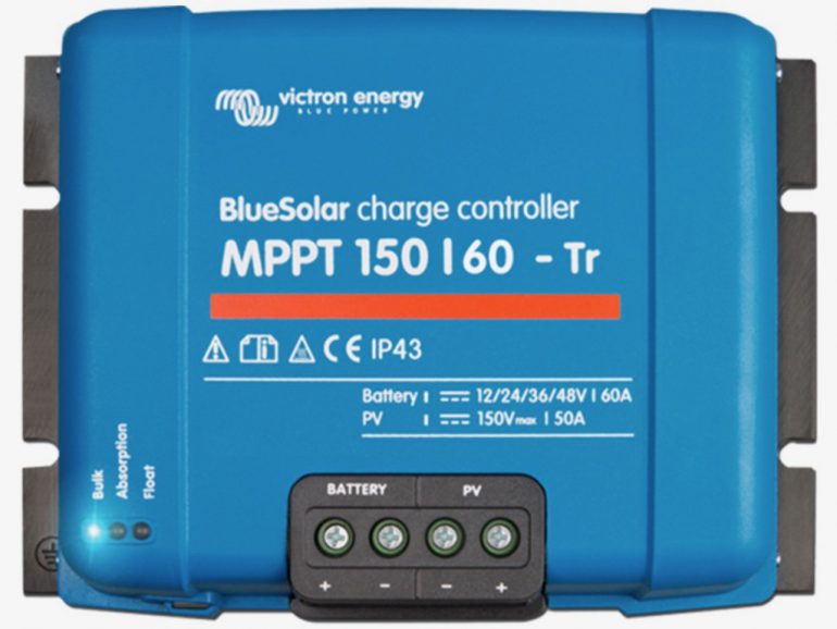
4. Solar
Two 595 watt solar panels with
a Victron Solar Controller
45 amps
Victron Energy produces some of the best engineered and highest quality electrical components in the marine industry. The U.S. Navy and Coast Guard use Victron equipment. Our solar controller is a Victron BlueSolar 150/6. It is lithium ready. Reprogramming for lithium is a simple matter of moving a selector switch.
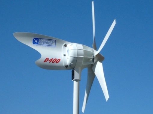
5. Wind Generator
Eclectic Energy D400 with a Flex-Charge controller
33 amps
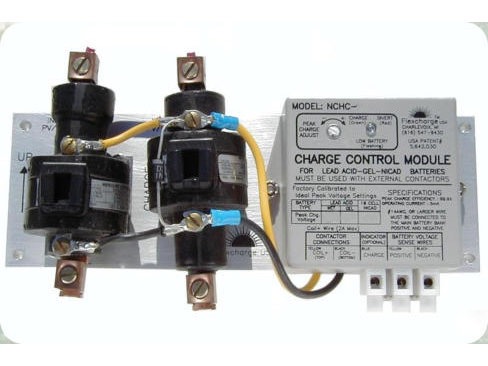
Eclectic Energy produces an excellent quality permanent magnet wind generator. The only problem with a permanent magnet generator is that it will continue to produce current as long as the wind blows. That can be a problem for any battery lead acid or lithium.
To manage that issue a charge controller must sense when the batteries have reached maximum voltage and then divert excess energy away from the batteries. The Flex-Charge NCHC controller will divert energy from the wind generator to some very low resistance, but very large resistors where the excess energy is turned into heat. The only trick is to ensure the diversion voltage is set correctly. This is done with an analog adjustment pot on the controller.
The Discharge Bus
The discharge leg is no big deal. There are no tricky parts on that side that both charge and discharge. There are basically three major consumers of 12V that branch out from the discharge leg
- The DC Circuit Breaker Panel
- The Anchor Windlass
- The Bow Thruster
Both the Thruster and the Windlass are high power users and have their own circuit protections. The DC panel has capacity for 100amps and 23 breakers that branch out into the boat for things like the refrigerator, cabin lights, navigation lights, instruments, autopilot, etc. These are the lower power consumers.
SOLAS – Safety of Life at Sea
The BMS disconnects all loads if the voltage goes below the 80% discharge threshold to protect the batteries from an early grave. But with apologies to battery huggers there are SOLAS issues that trump battery life. SOLAS is Safety Of Life At Sea. In my mind there are two SOLAS factors in play here.
- Keep the boat floating
- Radio Communications
Boats have bilge pumps for pumping water out of the boat that is coming into the boat. If the boat is taking on water, the last thing you want is the BMS turning off the bilge pump because the batteries are low. As far as I’m concerned, if the boat sinks, it sinks with dead batteries. The other factor is radio communications. I don’t want the BMS cutting power to my radios while I’m talking to someone about rescue.
To solve these two issues, I wired both the bilge pump and the radios around the BMS and directly to the batteries with appropriate fuses. If the BMS doesn’t like it, it can file a grievance with the Captain.
Cabling and Bus Hardware
Wire and Cabling
We weren’t just replacing batteries and using the existing cabling. We were separating distribution buses and going from 6 batteries to 9. I didn’t like the condition of the old cabling and 9 batteries require more interconnects than 6 so I used all new cabling and lugs. That way every cable is cut to the exact length needed and I know there are no loose lugs. Smaller guage wire is also required to wire in the BMS and relays.
For cabling, I used Ancor 2/0 tinned marine cabling, and for wiring, I used Ancor 16AWG tinned marine wire. Tinned marine wire should always be used on boats. The marine environment is harsh on wiring. If you don’t use tinned wiring, your untinned copper wires will turn into green goo.
Distribution Bus Hardware
The cables and wires are connected together with power posts, bus bars, terminal strips, etc. For the most part we used marine hardware made by Blue Sea Systems and wire terminals made by Ancor Marine.
Cable Lugs
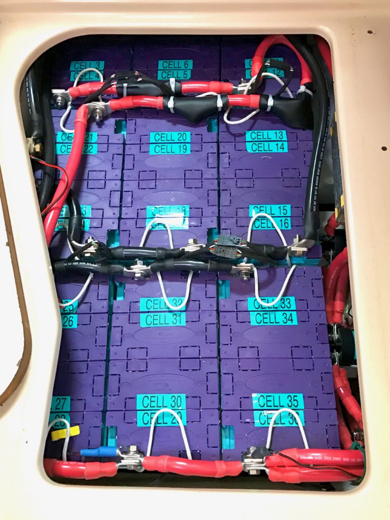
From CAD diagram there are 9 battery packs placed closely together with no space between them. That means the interconnect cables must run on top of the batteries. Unlike lead-acid batteries there are no terminal posts on top of the batteries for cables. To make all this work, I had to find some high quality 90° lugs for 2/0 cable. Those were ordered online from Remy Battery.
Final Assembly
With everything planned out and the preliminary work done, the project went together in 6 steps.
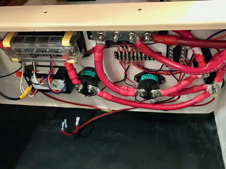
Step 1, Install bus hardware and relays.
The plan called for installing the relays and bus hardware on the bulkhead (wall) inside the battery compartment. Normally, that would be a bad idea because lead acid batteries can emit hydrogen gas which will degrade cable insulation. With lithiums, there’s no off-gasing and therefore no worries.
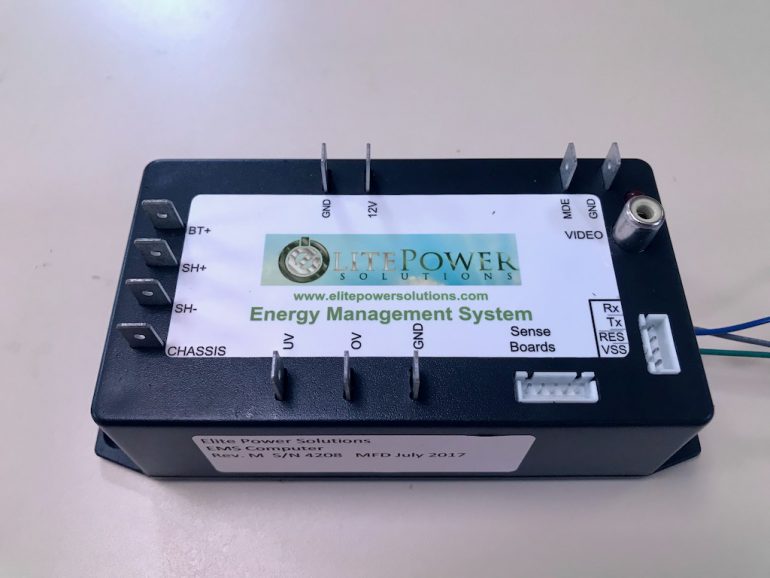
The BMS computer is at the bottom left of the photo. After the batteries were installed, I found it was nearly impossible to get to the computer so I have since relocated it behind the navigation instrument panel where it is much more accessible.
Step 2. Install BMS Computer
The BMS computer has a number of connections. It needs its own 12V power, it controls the Over/Under voltage relays, it needs to know the battery voltage, it needs to know how many amps are flowing in and out of the batteries, it has to monitor voltage and temperature of every cell through the sense boards, and it has to present all the information on the LCD display. Most of these connections are made with AWG 16 marine grade wire.
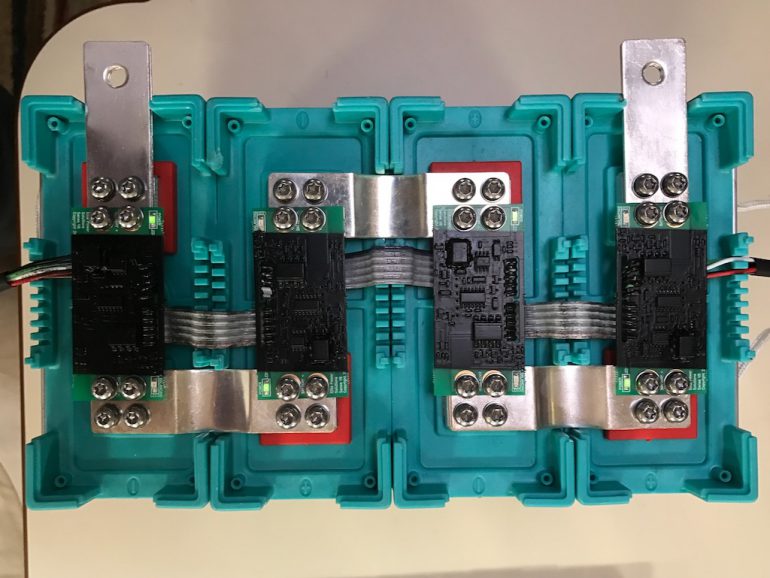
Step 3. Install the BMS Sense Boards
Batteries consist of cells. A cell consists of an anode and a cathode separated by an electrolyte. The voltage provided by each cell depends on chemistry. Small batteries like AA, C, D, etc., consist one 1.5V cell. Lead acid batteries consist of six 2.1V cells. Added together yields 12.6 volts. Lithium consist of four 3.2V cells. Added together the lithiums provide 13.2 volts.
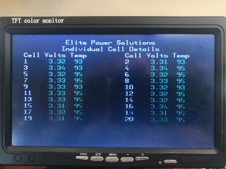
The BMS is capable of monitoring the voltage and temperature of each individual cell. The monitoring is accomplished by securing a small circuit board called a “sense board” to every cell and daisy chaining them all together so they can digitally send their information to the BMS. The sense boards come as a string of 4 and must be installed on each battery pack. On Karvi we installed 9 packs of 4 cells each for a total of 36 cells. The BMS allows me to see the voltage and temperature of every cell.
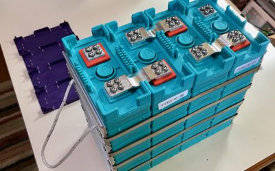
Step 4. Preassembly
Because of the tight space in the battery compartment, I assembled the entire battery bank on our main saloon table to make sure everything fit together with no problems.
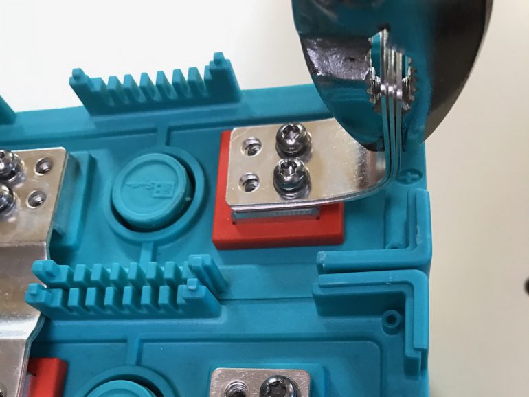
The terminals on GBS battery packs are flat pads with four 4mm screw holes. Needless to say, standard cable lugs will not attach to these pads. To solve the problem, Elite Power Solutions provides silver plated copper plates that bolt to the flat pads on the batteries on one end and bolt to cable lug on the other side. The plates are fairly thin. EPS recommended stacking the plates to handle higher current loads. With the 325amps needed by our bow thruster, we stacked 3 plates for each terminal. After bolting the plates to the batteries, I had to carefully bend each stack up by 90° to run the cables across the top of the battery bank.
With the sense boards installed and the terminal plates bent by 90° I could now work on the battery interconnects. The interconnects were fabricated from 2/0 cable and 90° lugs. I needed to arrange the batteries in such a way that the positive and negative poles of the battery bank were on opposite sides and corners and the negative and positive interconnects didn’t adjacent to each another presenting a risk of shorting. A little thought and big help from my Math major wife Nancy produced an elegant solution.
There are twelve short interconnects (6 red and 6 black), two medium and two long. Crimping duties were handled with a 10 ton hydraulic crimper available on Amazon. All cable connections were heat shrink sealed. The new marine standard for DC is Yellow and Red.
At the time of this installation, we couldn’t get any yellow 2/0 cable, so we used the old black and red standard.
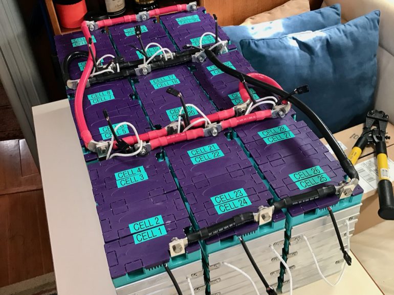
Step 5. Final Assembly and Installation
After verifying the configuration, cutting, crimping and test fitting the interconnects, and verifying each sense board was operational, it was time to disassemble the entire bank and reassemble it inside the battery compartment.
What you can’t see very well in the photo is the negative return side of the the cables coming back to the bank. There’s no need to separate the negative side into charge and discharge because the negative side doesn’t perform those functions. But there are some sizable cables returning to the compartment so they need a big bus bar as well. Also, the amount of current coming out and going into the bank is measured by the BMS on the negative side. A standard current measuring device is called a “shunt”. A shunt is essentially a calibrated conductor with a very small resistance that provides known voltage drop. By knowing the exact voltage drop, the BMS can use Ohms Law to calculate the amperage. The shunt is installed under the lip on the left side right next to the “CELL 22” label.
If you have a sharp eye you noticed the red cable connections at the top of the photo are wrapped with insulating rubber and zip tied. Rest assured all cable connections are now wrapped and tied per ABYC standards.
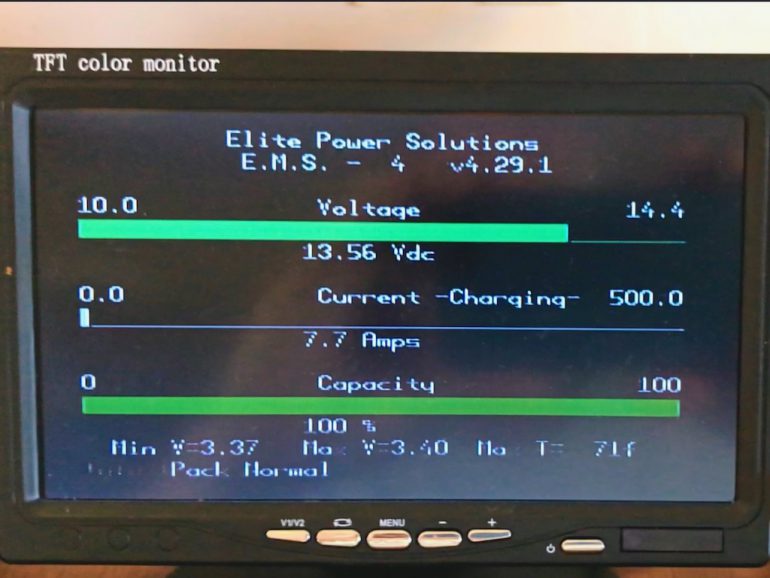
Step 6. Test, Monitor and Refine
The BMS has an LCD display with pages for Voltage, Current, Capacity and individual cell details. We closely monitored the system both on and off shore power for 3 days to watch for anomolies. We also checked tested each charging source. No problems were found. It wasn’t until about a year later, that we had an event.
At a remote anchorage in the Sea of Cortez we returned from a dinner with friends to find the BMS computer had shut down both relays. The solution was to kill power to the BMS computer and restart it by powering it back on. It’s the BMS version of Ctrl-Alt-Del. I found that was a little easier said than done. The BMS computer was in a really tight place inside the battery compartment next the the bank of the nine battery packs. After several contortions and scraped knuckles, I was able to get it restarted. Since then, I moved the BMS computer from the battery compartment to a place behind the navigation instrument panel where it is much easier to access. Since moving the computer, is has never repeated that performance.
Parts List
Below I’ve put together a parts list that covers most of the parts I used for the installation on Karvi. It doesn’t cover everything. There are still some things like wire terminals, terminal strips and low power distribution buses. Please use the parts list as a guideline to plan your own project.
*Elite Power Solutions: Since completing this project in 2016, EPS has decided to sell wholesale only and will no longer sell to the general public. Their BMS is proprietary, so if you want to use their BMS, you’ll have to get it from one of their distributors listed on their site. For the batteries themselves, you can buy them from one of their distributors or you can buy them from Alibaba if you are comfortable with that. I will mention, the Alibaba prices listed today are significantly lower than the prices we paid from EPS in 2016. Your mileage may vary.
| Item | Part# | Manufacturer | Supplier | Unit | Qty | Note |
| Lithium Ion LiFePO4 Battery Pack | GBS-LFMP100AHX | GB Systems | Elite Power Solutions* | 100Ah | 9 | Batteries – 900 amp hours |
| EPS BMS Computer | BMS | Elite Power Solutions* | Elite Power Solutions* | Ea | 1 | The BMS CPU |
| EPS BMS Sense Strings | Sense | Elite Power Solutions* | Elite Power Solutions* | Ea | 9 | Cell data & Battery Balancing |
| EPS Battery Terminal Plates | Plate | Elite Power Solutions* | Elite Power Solutions* | Ea | 60 | Silver plated copper |
| DC Contactor Relays 4000 amp | GA-200 | GigaVac | EV West | Ea | 2 | Charge/Discharge |
| Tinned Marine Battery Cable | 2/0 | Ancor Marine | Best Boat Wire | Foot | 60 | Red and Black |
| Tinned Marine Wire | 16 AWG | Ancor Marine | Best Boat Wire | Foot | 30 | Various colors |
| 4 Stud Bus Bar 600A | 2104 | Blue Sea Systems | Hodges Marine | Ea | 3 | Charge, Discharge, Ground |
| Power Post 3/8” | 2103 | Blue Sea Systems | Best Boat Wire | Ea | 1 | Distribution post to charge/discharge buses |
| 90 Degree Lug Connector | 6420L | Magna | Remy Battery | Ea | 10 | Battery Interconnects |
I’d like to hear from you. Please leave a comment below and tell me what you think.
All comments are manually moderated so it may take awhile for me to see and respond to your comment if we’re out at sea.
0 Comments